LEARN ABOUT
Seawater Barrier
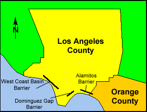
The Los Angeles County Department of Public Works operates and maintains three seawater barriers along Los Angeles County’s coastline. Often unnoticed because of their underground nature, these facilities serve as Los Angeles basin’s fresh water sentinels. They protect a significant portion of the area’s drinking water supply from ocean water, which constantly attempts to migrate into existing aquifers. Treated imported and reclaimed water is injected deep into the underground aquifers to block this inland migration of saltwater.
Hydrologic Basis for Seawater Intrusion:
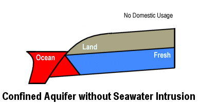
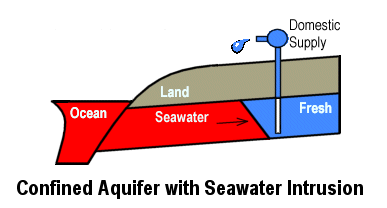
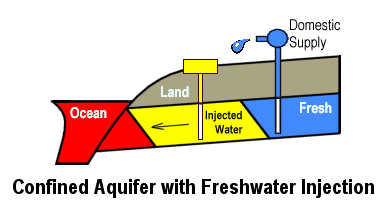
Fresh water which comes from the percolation of rain and river water into the ground accumulates within the different aquifers below the Los Angeles Basin. Originally there existed enough fresh water to completely displace any ocean water which might have migrated inland.
As larger and larger amounts of water are pumped up from underground for drinking water purposes, eventually there doesn’t exist enough fresh water to keep the ocean water at bay. At this point seawater intrusion begins to spread landward, compromising domestic water supply wells. By the end of 1950, such a situation existed within Los Angeles County.
One method which has been proven successful to combat this problem and is currently in use by the Department is to construct a series of injection wells along the coastline which recharge the domestic water supply with imported water and advance treated reclaimed water which has undergone microfiltration, reverse osmosis and disinfection. This technique attempts to establish groundwater elevations greater than or equal to the original elevations within the different aquifers.
Historical
Historical Perspective
In 1940 freshwater pumping wells along the coast of Los Angeles County began to be abandoned due to seawater intrusion. A cooperative study between the United States Geologic Survey’s Water Resources Division and the Los Angeles County Flood Control District to investigate this critical situation determined in 1943 that immediate action was necessary to restrain the situation. Of the different alternatives, only artificial groundwater recharge was found to be economically feasible. Although storm water spreading basins could be used to recharge local unconfined aquifers, which lie directly beneath the ground surface, something different and innovative was necessary to reach those deeper confined aquifers containing by far the most fresh water.
There exists three different barriers within LA County. The water which is injected is supplied by the Water Replenishment District, which purchases imported water from MWD, and reclaim water from West Coast Municipal Water District. The largest of these barriers is the West Coast Basin Barrier Project (WCBBP), which is an expansion of the original pilot study. The second largest barrier is the Dominguez Gap Barrier Project (DGBP). It began operation in 1971. The Alamitos Barrier Project was developed in conjunction with the Orange County Water District and crosses south of the County boundary. It went into operation in 1966.
The West Coast Basin Barrier Project
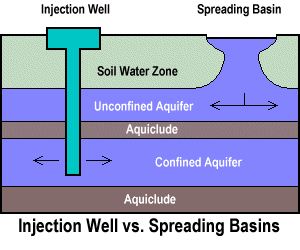
A bill passed by the California State Legislature in 1951, allowed the State Water Resources Board to fund various investigational groundwater recharge experiments being conducted by Los Angeles County utilizing injection wells. Results showed that seawater could be successfully displaced below a confined aquifer’s confining cap or “aquiclude”. This breakthrough, encouraged a pilot injection well program to be initiated along the coastline within the City of Hermosa Beach. By December 31, 1953, having proven that injection wells could be a useful tool to abate intrusion from the ocean, the Water Resources Board participation in the barrier project ceased. All capital costs since then to expand and improved the barriers have seen funded by the Los Angeles County Flood Control District.
The Dominguez Gap Barrier Project (DGBP)
The Second Largest Barrier is the Dominguez Gap Barrier Project (DGBP). It began operation in 1971. This barrier comprises of a line of 41 injection wells and 107 observation wells extend 12 miles from F Street to E street along the Dominguez Channel. The observation wells which are used to monitor water surface elevations and depth specific chloride levels, are located along the barrier alignment and placed between injection wells or situated off the immediate barrier alignment. Both reclaimed and imported water is used to be injected into the 200-foot Sand-Gaspur, 400-Foot Gravel and Gaspur Aquifers.
Dominguez Barrier alignment was selected based on comprehensive investigations which provided detailed geologic and hydrologic study of the Dominguez Gap area and determined the location, rate of movement, and rout of seawater intrusion. Based on these factors, the barrier alignment extends along the Dominguez Channel as north-to south alignment through Pacific Coast Highway and Southern Pacific Drive. The alignment then swerve west along Grant Street till it curves South-West along Alameda Street. To the west the alignment curves back inland along the E Drive and the then jogs one block south along Banning Boulevard to connect along the D Street. At D Street the alignment proceeds West through Avalon Boulevard and Wilmington Boulevard and then proceeds to the terminus located at Figueroa Street adjacent to the Interstate 110 Harbor Freeway
The Alamitos Barrier Project (ABP)
In conjunction with the Orange County Water District (OCWD), the Alamitos Barrier Project (ABP) was initially proposed and constructed in 1964, partially in Orange County and partially in Los Angeles County. The project was designed to protect the groundwater supplies in C, B, A, and I zones of the Central Basin of Los Angeles County and the southwest portion of the Coastal Plain area in Orange County from the intrusion of seawater through the Alamitos Gap area. The project, which is comprised of 43 injection wells to provide a freshwater pressure ridge and 4 extraction wells to form a trough which breaks the landward gradient of intruding seawater, is located near the Los Angeles-Orange County line about two miles inland from the mouth of the San Gabriel River. To monitor the project performance, there are 226 observation wells along the barrier alignment, between injection wells, and spread out both landward and seaward in the vicinity of the barrier. The observation wells are used to monitor water surface elevations and depth specific chloride levels.
The delineation of the alignment was based on geologic and hydrologic conditions, the route of seawater intrusion, the extent of seawater intrusion, geographic location, and available land. The alignment arcs across the Alamitos Gap and is landward of the seal Beach Fault.
Hydrogeology
Basin Hydrogeology
The natural ground water reservoirs beneath Los Angeles County consist of ground water basins which are grouped together under five major geographic areas. These areas are the Antelope Valley, Coastal Plain, San Fernando Valley, San Gabriel Valley, and Santa Clarita Valley. The basins within these locations are separated by natural geologic features which impede groundwater movement or by arbitrary political boundaries.
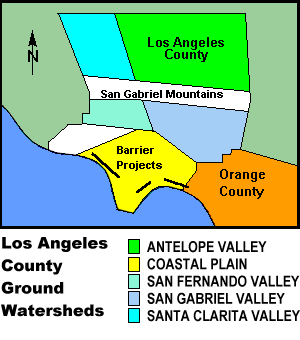
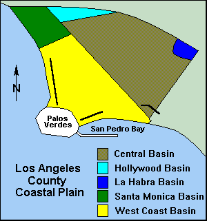
TheCoastal Plain of Los Angeles consists of five different basins: Central, Hollywood, La Habra, Santa Monica, and West Coast Basins. The Central and West Coast Basins are the two largest basins in the group. Two million residents of the Coastal Plain depend on groundwater that is protected by the barrier facilities for approximately 35 percent of their potable supply.
Central & West Coast basins
The Central Basin (CB) is bounded on the north-west by the Santa Monica Mountains, on the north-east by Merced and Puente Hills, and on the south-east by the Orange County Boundary. Imported water injected through the Alamitos Barrier project contributes to CB replenishment. The facility was primarily designed to protect the ground water supplies of this basin from intrusion through the Alamitos Gap area.
Similarly, the West Coast Basin (WCB) is bounded on the west and south by the Pacific Ocean, on the north by the Ballona Escarpment and on the east by the Newport – Inglewood Uplift. This fault forms a natural barrier to groundwater flows from the adjacent CB to the southerly WCB. Groundwater in this basin is primarily recharged from the two remaining barrier projects and from limited CB underflow. The Dominguez Gap Barrier facility was designed to prevent intrusion from San Pedro Bay, the West Coast Basin Barrier Project from the Pacific Ocean.
Reclaimed Water Recharge
Beginning in June of 1995, West Basin Municipal Water District began conveying highly treated recycled water to the West Coast Basin Barrier Project for recharge. The water is blended to a 50% ratio with imported water.
Facilities
Facility Descriptions
The design and construction of the Alamitos Barrier Project (ABP), Dominguez Gap Barrier Project (DGBP), or West Coast Basin Barrier Project (WCBBP) can best be described by dividing the discussion into four categories: General Description, Pressure Reducing Stations, Supply & Transmission Pipelines, and Injection Wells.
WCBBP
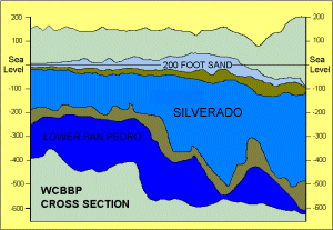
The West Coast Basin Barrier Project was expanded from the original experimental investigation at Manhattan Beach in 1953. It now consists of a line of 153 injection wells from the Palos Verdes Hills north to the Los Angeles International Airport, a distance of approximately nine miles. A combination of recycled and imported water is injected into the 200-Foot Sand, The Silverado, and The Lower San Pedro Aquifers. Complementing the injection wells are 296 observation wells. They serve as key indicators of system performance. The observation wells are either internodal wells placed between injection wells or located off the immediate barrier alignment. The wells are used to monitor water surface elevations and depth specific chloride levels.
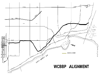
Alignment of the barrier was selected on the basis of geology, hydrology, and availability of rights-of-way. These factors resulted in the selection of Prospect Avenue as a suitable south-to-north alignment through Torrance, Redondo Beach, and Hermosa Beach. The alignment then jogs towards the coastline to connect to the original test project along the Santa Fe Railroad right-of-way in Hermosa Beach. To the north the alignment curves back inland along the right-of-way and then proceeds north from Roscrans Avenue within the Standard Oil property adjacent to Sepulveda Boulevard. At El Segundo Boulevard the alignment jogs two blocks west and then proceeds north to the terminus located at Imperial Highway.
Imported water is supplied through the Metropolitan Water District West Coast Feeder to the barrier at the terminal metering location, West Basin 28 (WB-28). Downstream of this connection, the water flow splits between the City of El Segundo’s water system and the barrier project. Downstream of a backflow preventer, reclaim water is supplied by the West Basin Municipal Water District. Secondary effluent is pumped from the Hyperion Plant to the West Basin Water Recycling Plant Title 22 and Barrier Treatment Facility and then on to the barrier pipeline transmission system.
Operation
Barrier Operation
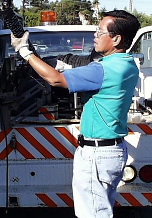
The Department’s three seawater barriers are operated with the goal of achieving and maintaining protective water surface elevations along the coast to prevent saltwater intrusion into inland drinking water supplies while minimizing the amount of water used for injection. The County satisfies this mission by gathering field data, then directing operations and maintenance at seawater barriers. Coordination can basically be broken into four different aspects: Evaluation, Operation, Coordination, and Maintenance.
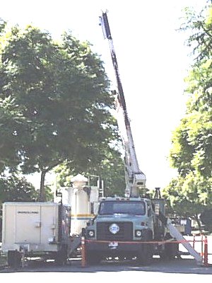
Evaluation of the current conditions within the proximity of the barriers requires a variety of field data to be gathered by Department personnel. Data such as groundwater surface elevations, chloride concentrations, injection rates, and injection pressures are collected manually by Department personnel. The data is reviewed and recorded into the Department’s operational database.
The Department coordinates with other outside agencies such as the Water Replenishment District of Southern California, Orange County Water District, West and Central Basin Municipal Water Districts, Metropolitan Water District of Southern California, Los Angeles City Department of Water & Power and the Regional Water Quality Control Board. Department staff provide the essential interagency cooperation fundamental to the successful operation of the barriers.
Maintenance is accomplished by Department field personnel. Barrier appurtenances such as shut off valves, air relieve valves, blow off valves, and pressure reduction valves require regular maintenance and repair. In addition, the Department employs a staff of professional drillers which specialize in highly technical repair work such as water well repair, well redevelopment, and subsurface grouting.
Injection Well
Injection Well and Components
Injection wells at the three seawater barriers vary in design and are constructed with transite (asbestos cement), low carbon steel, or stainless-steel casings and screens depending on the era of construction. The wells are equipped with an orifice plate or flow tube differential pressure flow measurement ports. These and other injection well header appurtenances are placed within a reinforced concrete vault. A six-inch lateral pipe leaves the distribution pipeline, which is equipped with a shut off valve, and connects to the header assembly.
Among the different injection well designs, there exist two major categories: single zone injection wells & dual zone injection wells. A single zone injection well is designed to provide groundwater recharge to a single targeted aquifer.
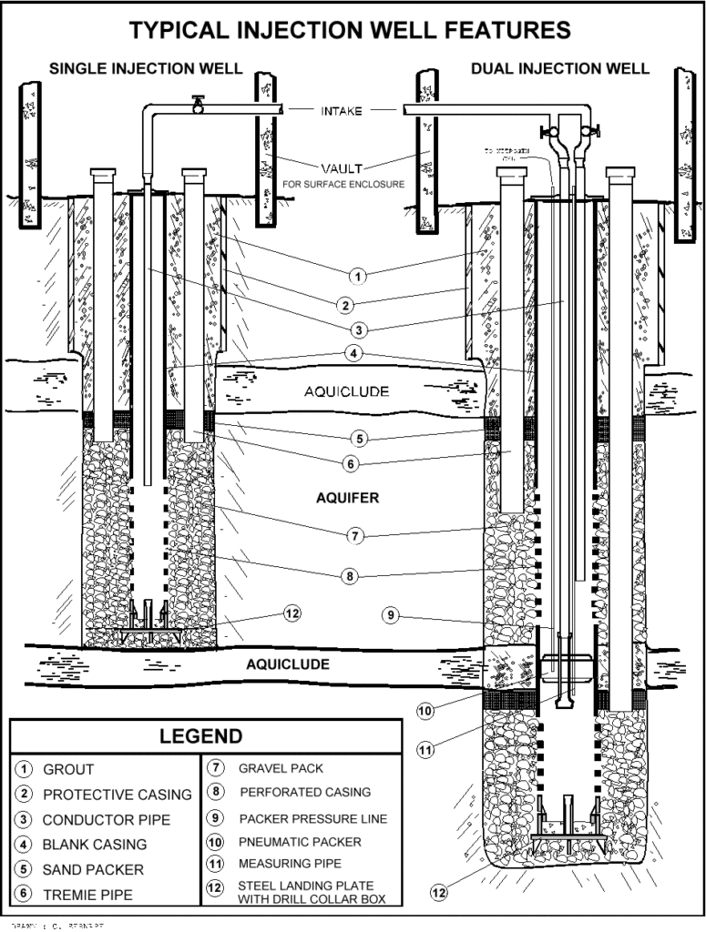
A dual zone injection well is designed to recharge two underground aquifers simultaneously or independently. It has a single casing perforated for communication in both the targeted aquifers separated by grouting of the annulus space at the aquiclude layer which separates the two. Inside the casing, hydraulic separation is maintained by an inflatable packer.
A packer provides hydraulic separation between two aquifers by an inflatable rubber assembly which is filled with nitrogen gas supplied from the ground surface. The vertical force that the packer must withstand to separate the two aquifers which have two different injection heads is developed by the skin friction between the rubber and the casing. This is controlled by the quantity of internal pressure maintained within the rubber bladder assembly.
Redevelopment
Well Redevelopment
The redevelopment of a well is the removal of fine material, organic or inorganic, from the well casing, perforations, gravel pack and surrounding aquifer. The process cleans out and opens up or enlarges the passages so that water may enter the well more freely. A well is first developed when originally constructed, but eventual clogging makes subsequent redevelopment necessary. One reason for clogging is the combination of a buildup of materials brought in by the injection water and the simultaneous or subsequent chemical changes in these particles. Another reason for clogging is bacterial growth. In these cases, the well is treated chemically and the dead organisms removed along with the fine particles.
Wastewater which is brought to the surface is processed through a mobile water treatment facility. The system removes the suspended solids found within the effluent, plus adjusts the Ph and turbidity prior to discharge into nearby storm drains
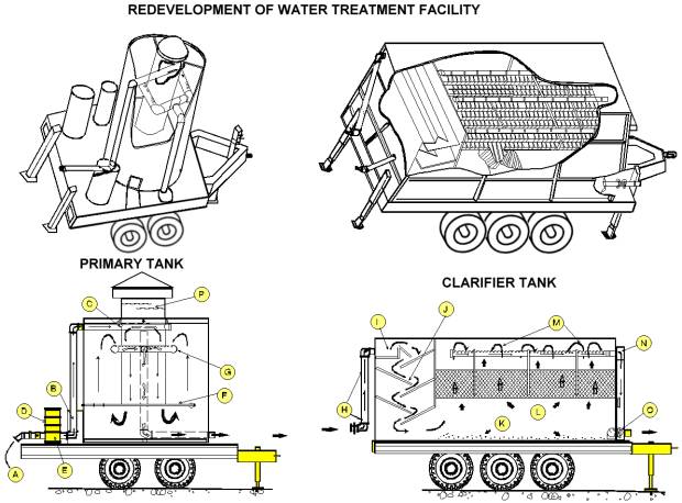
OPERATION OF THE TREATMENT FACILITY (refer to diagram)
The air-lifted wastewater enters the primary treatment system with intermittent high-energy flows through an inlet pipe (A). Between this point and the inlet energy dissipater (C), chemical additives are injected into the inlet pipe by an air driven metering pump (B). The chemical storage tanks (D) are required with an air driven agitator (E), which mixes one of several stock chemical prior to injections.
The functions of the primary tank are energy dissipation, flash mixing, primary coagulation of flocculent particles, and sedimentation. Quantities of wastewater, silty sands, and compressed air enter the central downcomer (P). The compressed air is separated from the flow of water and is vented through the roof downcomer. At this point, the velocity of the wastewater has been reduced as it is forced to travel through the downcomer. Flash mixing of wastewater and chemical additives is completed by the violent turbulence inside the downcomer as the wastewater moves down into the outer chamber of the tank. The air manifold (F) continues to aerate the treated wastewater to form large, flocculated particles. The heavier sand, silts, and flocculated particles settle to the bottom of the primary tank, as the upward velocity (1 fpm) is not adequate to carry the unwanted upward. The wastewater is collected off the top of the tank by the slotted discharge collector manifold (G). The manifold is designed to minimize “short circuiting” of wastewater through the tank, inducing near uniform discharge over the top cross section of the tank. The collected water is discharged through two outlet pipes, which further reduces the velocity of the wastewater. The wastewater from the primary tank is transferred to the rectangular fiberglass clarifier through two pipes (H). The incoming treated wastewater is uniformly distributed to the baffled flocculation chamber (J) by the inflow distribution chamber (I). Agglomeration of small light floc occurs as the wastewater moves down through the baffled flocculation chamber and into the sedimentation chamber at the bottom of the tank (K). As the wastewater moves through the sedimentation zone (L) and through the 60-degree tube settlers, all remaining flocculated settable solids are trapped on the inclined surfaces to settle to the bottom of the tank. The clear water at the top of the tube settlers is collected uniformly off the surface of the sedimentation chamber by three PVC discharge collector pipes (M). These pipes flow to the external discharge collector channel (N). The disposing of this treated wastewater through a flow meter (O) provides documentation of the quantities of water discharged through the treatment facility. Discharged water after reasonable treatment should meet the standards imposed by the Regional Water Quality Control Board as conditions to meet NPDES permit requirements.
Alternative
Alternative Studies
The Department’s groundwater injection barriers are successful at accomplishing their designed task. However, efforts continue to improve their effectiveness. As demand for drinking water in California increases, so does the cost to provide the imported water needed by all three barrier systems. Additionally, as barrier wells reach their designed lifeexpectancy, increasing demands are placed on well maintenance and replacement budgets. The need for an effective barrier system remains paramount, so alternative methods to stem seawater intrusion are periodically revisited. Although candidate alternatives may have been examined in the past and found not to be feasible, significant technical advances often make different approaches attractive and justify reconsideration. Listed below are a number of alternative seawater barriers which have been proposed.
Slurry Walls
The construction of a slurry wall involves the cutting of a bentonite slurry stabilized trench. This is accomplished using a large backhoe excavator suplemented by a clam shell (a large tool operated by a crane for the purposes of digging). The ditch is then backfilled with a mixture of soil-bentonite, a mixture of cement-bentonite, or plastic concrete materials that, when stabilized, forms an impervious barrier to seepage. Because of the need to cut a trench using heavy equipment, this procedure has limitations with respect to disturbances of existing utilities which are often located near the ground surface.
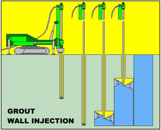
Grout Curtains
Grout curtains are constructed by drilling 2- to 6-inch diameter holes along a single line or multiple parallel lines. Grout is then injected into the holes under pressure to fill the surrounding soil pores or rock fractures. By placing these holes on a tight enough spacing ( typically 3 to 10 foot spacings ), a grout barrier of variable thickness is created. Grout curtains can be installed to most any depth and can be surgically injected to treat specific depth zones.
Air Injection
Air injection is used in the development of oil and gas fields and during tunneling to cutoff the flow of water. Compressed air injected into the groundwater attempts to cause a piezometric rise in water level that can be used to alter groundwater gradients and flow directions. Air entrained in soil pores causes an overall decrease in the permeability of the aquifer which could be used to reduce flow across specific zones.
Bio Wall
This technology involves the injection of starved bacteria cultures into the pores of the aquifer media to develop a biological subsurface plug or bio-wall. This method uses microbial growth to fill in the void space found in all soils, thus decreasing it’s permeability. The wall is maintained by periodic injection of nutrients to feed the bacteria in specific zones. This type of wall has only been evaluated by modeling and in the laboratory.
Telemetry
Barrier Telemetry System
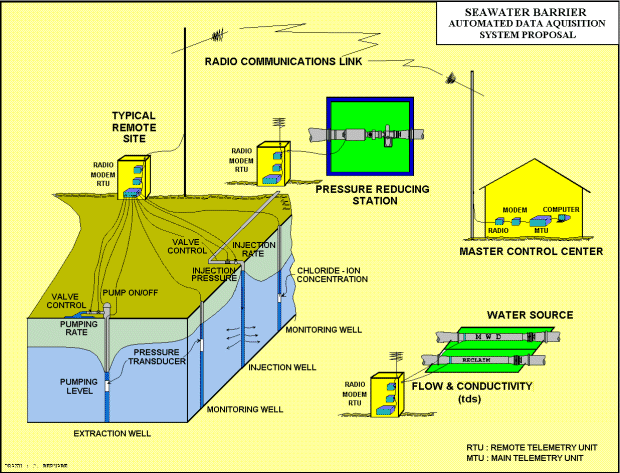
A pilot study which the Department has initiated seeking to improve efficiency within the seawater barriers is to develop a state-of-the-art data management, remote monitoring, and operations system. Data will be fed to a Departmental control facility via telephone, radio, or satellite linkup. The data management system will be capable of collecting, storing, analyzing, and graphically presenting real time barrier status information. The implementation of a reliable real time data collection and remote monitoring system will improve the Department’s existing barrier controls system by enabling on-line visibility and direction of operations.
Depicted below is the proposed telemetry system concept.
Acknowledgments
This Operations Section Unit Summary was prepared in the Stormwater Engineering Division, Operations Section of the Los Angeles County Department of Public Works under the direction of Gary Hildebrand, Operations Section Head. The following people contributed to the completion of this website:
General Supervision
E. Gerlits & J. Burton
Coordination, layout & write-ups
W. Saunders & S. Hamad
Graphic Design & Art Production
M. Ang & C. Bernabe
References
Barneich, John, Draft Report: Alternative Seawater Barrier Feasibility Study. Report Prepared by URS Greiner Woodward Clyde, dated 1999: Los Angeles County Department of Public Works, Los Angeles, CA. pp 1-1, 3-1 through 3-4 & Fig. 29.
Bolton, Joseph M., Proposal for Study of Deficiencies West Coast Barrier Project. Proposal prepared by The Earth Technology Corporation, Dated 1985: The Earth Technology Corporation, Long Beach, CA. p. 1.
Burton, John A., Saunders, William F., Bernabe, Cris B., West Coast Basin Barrier Project Hydrologic and Operations Report October 1995-September 1997. Prepared by Hydraulic/ Water Conservation Division, dated 1999: Los Angeles County Department of Public Works, Alhambra, CA. pp. 8-9.
California Department of Water Resources, Sea-Water Intrusion in California, Bulletin No. 63. Report prepared by the Los Angeles County Flood Control District, dated 1955: State of California Department of Water Resources Division of resources Planning, Sacramento, CA. pp 31-35.
Cooper, David K., Barrier Injection Well Redevelopment Manual. Lettergram prepared by Water Conservation Division, dated 1971: Los Angeles County Flood Control District, Los Angeles, CA. p.1.
Dosi, Ramesh, Rancilo, James, Alamitos Barrier Project Annual Report on the Control of Seawater Intrusion 1883-84. Report prepared by Water Conservation Division, dated 1984: Los Angeles County Flood Control District, Los Angeles, CA. p.1.
Farag, George S., Groundwater Conditions in Los Angeles County for the Current Year October 1, 1984 to September 30, 1985. Report prepared by the Groundwater Hydrology Unit, Hydraulic/Water Conservation Division, dated 1985: Los Angeles County Department of Public Works, Alhambra, CA. pp. 2-3.
Jackson, Wayne, Seawater Barrier Automation and Telemetry Study. Request for Proposal prepared by Hydraulic/ Water Conservation Division, dated 1999: Los Angeles County Department of Public Works, Alhambra, CA pp. 1-2.
Lafferty, Dan, Seawater Barrier Operations Mission Study. Report Prepared by Hydraulic/ Water Conservation Division, dated 1995: Los Angeles County Department of Public Works, Alhambra, CA. pp.1.1-4.1.
Laverty, Finley B., Van der Goot, Herbert A., Development of a Fresh-Water Barrier in Southern California for the Prevention of Sea Water Intrusion. Article prepared by Hydraulic Division, Los Angeles County Flood Control District, dated 1955: Journal American Water Works Association Vol 47, No. 9, United States: pp. 886-887.
Lipshie, Steve R., Larson, Robert A., The West Coast Basin, Dominguez Gap, and Alamitos Seawater Intrusion Barrier System, Los Angeles and Orange Counties. Prepared by Materials Engineering Division: Los Angeles County Department of Public Works, Alhambra, CA.. pp. 1-2.
Los Angeles County Department of Public Works, Hydrologic Report 1993-94. Report Prepared by Hydraulic/ Water Conservation Division, dated 1995: Los Angeles County Department of Public Works, Alhambra, CA. p. “PG2”.
Simmons, Robert L., West Basin Water Recycling Plant NPDES Monitoring Report for First Quarter 1999. Report prepared by West Basin Municipal Water District, dated 1999: West Basin Municipal Water District, Los Angeles, CA. p. 2.
Solari, Fernando J., Seares, Frederick D., Evans, Charles C., West Coast Basin Barrier Project 1963-1967. Report prepared by Water Conservation Division, dated 1968: Los Angeles County Flood Control District, Los Angeles, CA. pp. 1.9-1.13.
Zargaryan, Araik, Dominguez Gap Barrier Project Hydrologic and Operations Report 1996-97. Report prepared by Hydraulic/ Water Conservation Division, dated 1998: Los Angeles County Department of Public Works, Los Angeles, CA. p.1.
Zargaryan, Araik, Alamitos Barrier Project Hydrologic and Operations Report 1996-97. Report prepared by Hydraulic/ Water Conservation Division, dated 1998: Los Angeles County Department of Public Works, Los Angeles, CA. p.1.
Zilbauer, E.J., Van der Goot, H.A., Bruington, A.E., Ingram, A.A., Report to the California State Water Resources Board on Investigational Work for Prevention and Control of Sea Water Intrusion. Report prepared by the Hydraulic Division, dated 1955: Los Angeles County Flood Control District, Los Angeles, CA. pp.3-29.
